This is the Site Operations golf cup challenge. We took a button out of an old mouse for the button in the bottom of the pen holder cup. Using an Arduino Micro and a relay, we will turn on a spinning light when a golf ball drops into the cup and triggers the button.
The only thing I had to purchase was an extension cord to splice into. The rest of the stuff I used I had as either leftovers or spare parts.
-
Pencil cup holder thing. Something like this would work. $1
-
Arduino Micro. $25
-
Relay. I found a 4 channel relay like this. $9
-
6' Extension cord to splice into. $1
-
Tie wire. Duct tapes heavy duty cousin. $1
-
1 10k resister. $0.20?
-
1 switch out of a crusty old mouse. $0.10? I found an old PS2 mouse to cannibalize.
-
Soup can lid
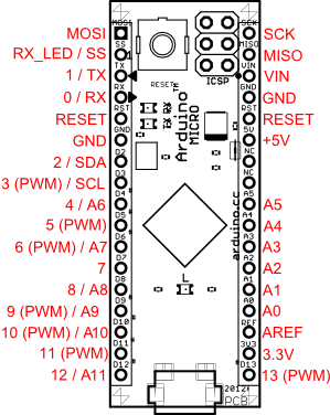
Here you can find the pinout. This will be important. From here on, we will refer to the Arduino Micro as AM.
There are clearly marked pins on the relay board. Wiring is as follows:
vcc -----> AM 5v power
gnd -----> AM gnd
IN1 -----> AM pin 2
For the mouse button, you will have to bear with me since I don't know the correct terms, I don't care to learn them today, and there are no markings on this switch. Instead, I have prepared for you some ascii art. Enjoy. :)
NOTE: If you want to see what these buttons look like, here is an image I found while googling around: internal mouse button
 ___________
 |    ^    | ------------------> Pin -> AM pin 10
 |  *****  | ---> Red Button for orientation
 |    ^    | ------------------> Pin -> 10k resistor -> AM gnd
 |         |
 |    ^    | ------------------> Pin -> AM 3v vcc
 |_________|
Again, bear with me since I don't know what I am doing here. I found this extension cord at the dollar store. As such, it was 1 dollar. Furthermore, it doesn't have a ground wire. There are only 2 wires. I chose to splice into the wire that ran to the fatter "Polarized" (or something) bit that goes into the wall. More ascii art to describe how I did that:
NOTE: Since the relay that I had was a 4 channel, there were 4 such places to wire it in.
We just need the one. If you use one that is different than the IN1, you will have to change
that accordingly. Duh.

                            |- - - - -|
                            |         |
                            |  Relay  |
                            |         |
                            |_________|
                           |(+)|(+)|(+)|
                            ||| |||
                            ||| |||
                             || ||
---------------Fat end wire -*| |*--Fat end wire----------------------------------
--------------------------Other wire----------------------------------------------
^                                                                                 ^
Extension cord end that plugs into wall            End that you plud the light into
Since the goal of this project was to engage the button when a golf ball drops into the cup we need to wire up the cup. This cup was a wire mesh so it was really easy to use tie wire to stabilize the button. Since we needed to engage if the bottom of the cup was impacted anywhere, I opted to cut down slightly a soup can lid so that it fit inside the bottom of my pencil holder cup. I used a cris-cross pattern with the tie wire to achieve stability for both the button, and the soup can lid that hovers over the button. More ascii art.
    |               |
    |               |
    |               |  Side view(sort of)
    |  ____Lid____  |
    |     [***]     | <--- Button
    |      ^^^      |
    |      \\\      |
    |       --------|-----> Wiring to the AM
    |_______________|
If you upload the include sketch(./golf_cup.ino) to the Arudino micro after you have it wired as described, it should work. Or something.
Maybe if I cared I would include an image of the finished cup. But I don't. Who else would even read this?